![]() Select the Operation | Graphics Display Window | Auto
Insert Moves menu option. The Automatically
create clearance moves dialog box appears.
Select the Operation | Graphics Display Window | Auto
Insert Moves menu option. The Automatically
create clearance moves dialog box appears.
Once you import your part program and have finished Path Optimization, you should ensure that when the probe moves to measure your features, it will not collide with your part. Collision Avoidance is accomplished by inserting move commands. To do this, use PC-DMIS’s Auto Insert Move menu option to automatically create clearance moves for a range of features:
Note: Move commands can be placed between the range of features specified, but not prior to the first feature. A clear path is assumed to the probe start position and the first feature.
![]() Select the Operation | Graphics Display Window | Auto
Insert Moves menu option. The Automatically
create clearance moves dialog box appears.
Select the Operation | Graphics Display Window | Auto
Insert Moves menu option. The Automatically
create clearance moves dialog box appears.
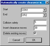
Automatically create clearance moves
Select the first feature for the range of features from the Start list.
Select the last feature for the range of features from the End list.
Type a value in the Collision safety box. This value provides a buffer zone around the probe tip so that PC-DMIS considers close misses as collisions.
Type a value in the Insert clearance moves box. This value defines the distance that the probe moves away from the part when it detects a collision while trying to move the probe to the next feature. PC-DMIS attempts to go directly to the next feature, but compensates for collisions by inserting clearance move commands. It continues this process until it defines a collision free path to the next feature. More than one move command may be inserted between features.
Select the Delete existing moves check box if you want to delete any pre-existing move commands in the part program.
![]() For Dual Arm programs, PC-DMIS will insert
“Move Exclusive” commands as necessary to guard against the two arms colliding
during execution.
For Dual Arm programs, PC-DMIS will insert
“Move Exclusive” commands as necessary to guard against the two arms colliding
during execution.