Click 3D
Scan ![]() from
the Auto Geometry Features toolbar or select the Features
| 3D Scan menu item. The 3D Scan
dialog box appears.
from
the Auto Geometry Features toolbar or select the Features
| 3D Scan menu item. The 3D Scan
dialog box appears.
A 3D Scan feature allows you to create a scan feature that will be imported into PC-DMIS as a Patch Scan. See the "Performing a Patch Advanced Scan" topic in the Core PC-DMIS help file.
To Create a 3D Scan Auto Geometry Feature:
Click 3D
Scan ![]() from
the Auto Geometry Features toolbar or select the Features
| 3D Scan menu item. The 3D Scan
dialog box appears.
from
the Auto Geometry Features toolbar or select the Features
| 3D Scan menu item. The 3D Scan
dialog box appears.
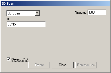
3D Scan dialog box
If needed, provide an ID for the 3D Scan feature in the ID box.
Specify the Spacing value at which points will be added as part of the 3D Scan feature.
Click on the CAD to define the start point of the 3D scan boundary. Continue clicking on the CAD surface to define the shape and extent of the 3D Scan boundary. Each click will add a new vertex of two new lines to the end of the last line and back to the start point.
Note: You can adjust the location of each of the vertices of the boundary by selecting the needed green line near the vertex that you want to move (the line will highlight in red) and dragging the vertex to the new location.
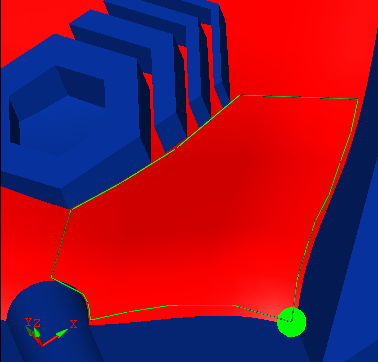
Example: Defining the 3D Scan boundary and selecting CAD
Select the Select CAD option.
Select the CAD surface for which the 3D Scan will be measured by clicking on the CAD. The selected surface is shown in a red highlight color.
Note: The resulting Patch Scan in PC-DMIS will create points separated by the spacing value on the selected surface within the defined boundary.
Click Create to add the 3D Scan feature to the Inspection Plan, or click Close to close the dialog box without saving.
Click Remove Last to remove the 3D Scan feature that was last added to the Inspection Plan.