Click
Location Dimension ![]() from
the Dimensions toolbar
or select the Dimension | Location menu item. This opens the Feature Location dialog box.
from
the Dimensions toolbar
or select the Dimension | Location menu item. This opens the Feature Location dialog box.
To Create a Location Dimension:
Click
Location Dimension ![]() from
the Dimensions toolbar
or select the Dimension | Location menu item. This opens the Feature Location dialog box.
from
the Dimensions toolbar
or select the Dimension | Location menu item. This opens the Feature Location dialog box.
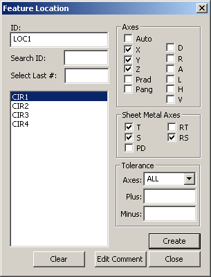
Feature Location dialog box
If needed, type an ID for this location dimension in the ID box.
Select the features for which location dimensions will be created by:
Selecting the features by clicking the feature name from the list.
Typing the needed feature name in the Search ID box and the feature will be highlighted in the Feature list box when you press the TAB key.
Selecting the last of a certain number of features by typing the needed number in the Select Last # box. For example, if you wanted to select the last four features that were created, simply type 4 and press the TAB key. PC-DMIS will highlight the features selected in the Feature list box.
Click Clear to clear the previously selected features.
Select the appropriate Axes and Sheet Metal Axes for the selected feature(s). If you select Auto, Inspection Planner will automatically select the default Axes and Sheet Metal Axes. For example, if an IP point is selected, then the X, Y, Z, and T (vector) axes will be selected.
Provide the Tolerance values for each axis selected, by selecting the axis from the Axes drop-down box and typing the Plus and Minus tolerance values.
If the same tolerances are wanted for more than one axis, select "ALL" from the Axes drop-down box and type the Plus and Minus tolerance values. These values are applied to all of the Axis types.
To add a comment to the location dimension commands, click Edit Comment to open the Edit Comments dialog box.
Click Create to add location dimension(s) to the Inspection Plan, or click Close to close the dialog box without saving.