Select Angle
Dimension ![]() from
the Dimensions toolbar
or select the Dimension | Angle
menu item. This opens the Angle Dimension
dialog box.
from
the Dimensions toolbar
or select the Dimension | Angle
menu item. This opens the Angle Dimension
dialog box.
To Create an Angle Dimension between two features:
Select Angle
Dimension ![]() from
the Dimensions toolbar
or select the Dimension | Angle
menu item. This opens the Angle Dimension
dialog box.
from
the Dimensions toolbar
or select the Dimension | Angle
menu item. This opens the Angle Dimension
dialog box.

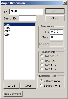
Angle Dimension dialog box
If needed, type an ID for this angle dimension in the ID box.
Select 2 features for which angle dimensions will be created by:
Selecting the 2 features by clicking the feature names from the list.
Typing the needed feature name in the Search ID box and the feature will be highlighted in the Feature list box when you press the TAB key.
Click Last 2 to select the last two features from the list.
Click Clear to clear the previously selected features.
Provide the Plus and Minus Tolerance values for the angle dimension(s). PC-DMIS calculates the Nominal angle between two features. The nominal value provides distance by which the tolerance values will be evaluated. You may also apply a previously used tolerance value by selecting it from the drop-down list. The last 10 tolerance values are stored.
Choose the Relationship option for a 2 Dimensional angle type to which the angle will be relative. The To Feature option uses the feature vector for the relationship.
Specify the Distance Type. The 2 Dimensional option will measure in a two-dimensional plane relative to the specified feature vector or XYZ axis. For 2 Dimensional options you must also specify the Orientation and Relationship options. 3 Dimensional option will measure the best fit angle created between the two features.
To add a comment to the angle dimension commands, click Edit Comment to open the Edit Comments dialog box.
Click Create to add the angle dimension to the Inspection Plan, or click Close to close the dialog box without saving.