Click Edge
Scan ![]() from
the Auto Geometry Features toolbar
or select the Features | Edge Scan menu
item. The Edge Scan dialog box
appears.
from
the Auto Geometry Features toolbar
or select the Features | Edge Scan menu
item. The Edge Scan dialog box
appears.
An Edge Scan feature allows you to create a scan feature that will be imported into PC-DMIS as a Perimeter Scan. See the "Performing a Perimeter Advanced Scan" topic in the Core PC-DMIS help file.
To Create a Edge Scan Auto Geometry Feature:
Click Edge
Scan ![]() from
the Auto Geometry Features toolbar
or select the Features | Edge Scan menu
item. The Edge Scan dialog box
appears.
from
the Auto Geometry Features toolbar
or select the Features | Edge Scan menu
item. The Edge Scan dialog box
appears.
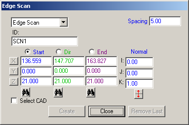
Edge Scan dialog box
If needed, provide an ID for the Edge Scan feature in the ID box.
Specify the Spacing value at which points will be added as part of the 2D Scan feature.
Define the Start, Direction (Dir), and End points along the perimeter of the CAD feature that will be selected. To do this:
Select the radio button next to Start. This is selected by default when you first open the Edge Scan dialog box.
Click on the CAD near the location where the Edge Scan will begin. The XYZ values are derived from the Start point location, a blue start point indicator is displayed on the CAD, and the Dir radio button is now selected automatically. The Normal vector for the surface that was clicked is also provided
Click on the CAD near the location on either side of the start point to define the direction in which the scan will proceed. The XYZ values are derived from the Direction point location, a green direction point indicator is displayed on the CAD, and the End radio button is now selected automatically.
Click on the CAD near the location where the Edge Scan will finish. The XYZ values are derived from the End point location, a purple end point indicator is displayed on the CAD, and the Start radio button is now selected again automatically.
Note: The selection of these points will cycle through each of these points until you are satisfied with the Edge Scan definition. You can however select the radio button for the point that you would like to define at any time. You may also click directly on the point indicator and drag it to the desired location.
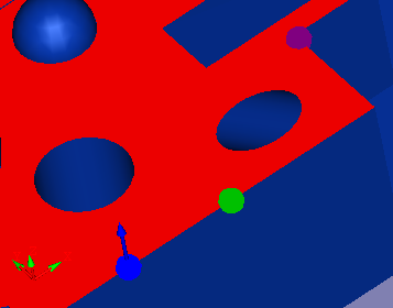
Example: Selecting Start, Direction, End points and CAD surface
Click the Find
Nearest CAD Element button ![]() to
find the nearest CAD element in the Graphics Display window based on the
XYZ location and any selected axis (or axes). This is especially useful
when you have typed the XYZ values and need to update these values with
the closest edge point on the CAD.
to
find the nearest CAD element in the Graphics Display window based on the
XYZ location and any selected axis (or axes). This is especially useful
when you have typed the XYZ values and need to update these values with
the closest edge point on the CAD.
Click the Flip
Vector button ![]() to
flip the Normal vector.
to
flip the Normal vector.
Select the Select CAD option. When this option selected, the other parameters in the dialog box become unavailable.
Select the 2D CAD surface for which the Edge Scan will be measured by clicking on the CAD. The selected surface is shown in a red highlight color.
Click Create to add the Edge Scan feature to the Inspection Plan, or click Close to close the dialog box without saving.
Click Remove Last to remove the Edge Scan feature that was last added to the Inspection Plan.