Click Alignment
![]() from
the Tools toolbar or select
the Tools | Alignment
menu item. This opens the Alignment
dialog box.
from
the Tools toolbar or select
the Tools | Alignment
menu item. This opens the Alignment
dialog box.
If needed, type an ID for the alignment in the ID box.
Click Iterative to open the Iterative Alignment dialog box.
Aside from standard alignments, capability exists to create Iterative (3-2-1)Alignments using Inspection Planner.
To Create an Iterative Alignment:
Click Alignment
![]() from
the Tools toolbar or select
the Tools | Alignment
menu item. This opens the Alignment
dialog box.
from
the Tools toolbar or select
the Tools | Alignment
menu item. This opens the Alignment
dialog box.
If needed, type an ID for the alignment in the ID box.
Click Iterative to open the Iterative Alignment dialog box.
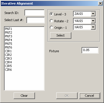
Iterative Alignment dialog box
Select the proper axis from the Level - 3 combo box.
Select the three (or more) features from the feature list on the left for the level.
Note:
When selecting features use the following dialog box options:
· Typing the needed feature
name in the Search ID box and
the feature will be highlighted in the Feature list box when you press
the TAB key.
· Selecting the last of a certain
number of features by typing the needed number in the Select
Last # box. For example, if you wanted to select the last four
features that were created, simply type 4 and press the TAB key. PC-DMIS
will highlight the features selected in the Feature
list box.
· Click Clear
to clear the previously selected features.
Click Select or the Rotate - 2 radio button.
Select the proper axis from the Rotate - 2 combo box.
Select the two (or more) features from the feature list on the left for rotation.
Click Select or the Origin - 1 radio button.
Select the proper axis from the Origin - 1 combo box.
Select one feature from the feature list on the left for the origin.
Type in the proper value for the Fixture tolerance. This value allows you to provide a fitting tolerance value against which PC-DMIS compares feature elements making up the iterative alignment to their theoretical values.
Note:
If after fitting the measurement values to the theoretical values, one
or more of the input features have an error along their assigned datum
axis that exceeds this tolerance value, PC-DMIS displays an error message.
The message shows the errors along each of the datums. You will have the
choice to accept the datum as it is and continue with the rest of the
part program, or to cancel the part program execution.
PC-DMIS can only use the Fixture
tolerance value if you used more than the minimum number of points needed
to create the feature. For example, if you are measuring a plane, the
minimum number of points needed for that plane is usually three points.
However, if you wanted to use the fixture tolerance value, you would need
to measure at least four points. If you use only three points then only
one solution exists and PC-DMIS cannot adjust or re-iterate.
Click OK. The iterative alignment will get added to the list of alignments in the main Alignment dialog box:
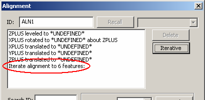
Iterative Alignment added to list of alignments
Click OK from the main Alignment dialog box will add this alignment to the Inspection Plan.