Click the Display Symbols
icon ![]() to
open the Display Symbols dialog
box.
to
open the Display Symbols dialog
box.
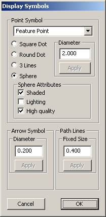
Display Symbols dialog box
This dialog box lets you change how different symbols are displayed in the Graphics Display window.
Available symbols you can modify include the Point Symbol, the Arrow Symbol, and Path Lines. Whenever you make a change to one of the check boxes or option buttons, PC-DMIS will apply that change automatically so you can see what effect it will have. PC-DMIS will only save your changes once you click the OK button. To see changes to the symbols' sizes click the appropriate Apply button.
Point Symbol Area
Point Symbol drop-down list: This list defines the type of Point to modify. You can choose either CAD Point, or Feature Point. The default item is Feature Point.
Diameter / Width in Pixels box: This box defines the size of the point symbol. Square Dot and Round Dot symbols use Width in Pixels; 3 Lines and Sphere use Diameter in part program units. Note that the maximum size for Round Dot is based on the computer's physical video card. If the size exceeds the limits of the current computer's video card, it will simply display the symbol at the largest size available to the current system's video card.
Square Dot option: This option displays the point symbol as a square dot. This is the quickest symbol for PC-DMIS to draw.
Example Square Dot symbol
Round Dot option: This option displays the point symbol as a round dot.

Example Round Dot symbol
Note: Square Dot and Round Slot symbols are drawn flat on the screen and may be clipped by the CAD model.
Three Lines option: This option displays the point symbol as a three-lined cross hair.
Example Three Lines symbol
Sphere option: This option displays the point symbols as a sphere. This is the slowest symbol for PC-DMIS to draw, especially if you have all the attributes selected.
These check boxes become available if you select the Sphere symbol. They provide you with additional attributes to further control the display of a sphere symbol in the Graphics Display window.
Shaded - This check box produces a shaded (opaque) sphere symbol.
Lighting - This check box adds OpenGL lighting to the sphere symbol.
High Quality - This check box produces a smoother looking sphere symbol.
While these check boxes improve the image quality of the sphere symbol, they will also cause a slight increase in the time it takes to draw the sphere symbols whenever the screen gets refreshed.
Some Sphere Examples:
|
|
Shaded, High Quality |
|
|
Lighting, High Quality |
|
|
Shaded, Lighting, High quality |
Arrow Symbol Area
This box controls the diameter size (in part program units) of the arrows displayed in the Graphics Display window. The size of the actual arrow in the display will change only if the Shaded check box is selected. The value is in part program units.
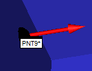
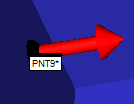
Some Arrow Examples:
|
|
Smaller Arrow |
|
|
Larger Arrow |
Path Lines Area
This area controls the fixed diameter size (in part program units) of the path lines displayed in the Graphics Display window. Fixed size means the path lines will not change size on the screen when zooming in or out on part model.
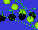
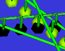
Some Path Line Examples:
|
|
Default Size |
|
|
Increased Diameter |