The CAD Transform dialog box allows you to transform (translate, scale and rotate) individual parts of your CAD model. If needed, you can keep a copy of the original unmodified CAD part, as well as create a new coordinate system for the transformed CAD part.
To transform a CAD part, select a cad part from the assembly list, access the CAD Transform dialog box from the CAD Assembly dialog box by clicking Transform. Make the needed changes and click OK or Apply.
![]()
CAD Transform dialog box
The CAD Transform dialog box make use of the following options:
|
Dialog Box Item |
Description |
|
Keep Original |
This check box lets you keep a copy of the original, unmodified CAD model. |
|
Create New Coordinate System |
This check box lets you create a new coordinate system from the newly translated CAD model. Currently this option is disabled in Inspection Planner. You can create a new Coordinate System using the CAD Transform dialog box (Operation | Graphics Display Window | Transform) within PC-DMIS, if needed. |
|
Translate |
This area defines the XYZ offsets to translate the selected CAD part. You can either type the specific relative distance that the part should be moved from its current location, or you can use the Select button to select a specific CAD entity to which the coordinate system will move. See "Transforming by Selecting" below. |
|
Scale |
This area defines how the CAD part will be scaled. This can be useful for fixing parts that are not scaled correctly due to improper measurement unit identification. For example, if the part is sized for millimeter units but you know they should be inch units, you would scale the part by 25.4. The Uniform check box uniformly scales the part. If you want to scale a selected axis of the part, clear the Uniform check box. Leave the value as 1 for axes that you don't want scaled, and change the axis that you want scaled. You can also scale axes by negative values. This is useful if you want to mirror an axis. In this case you would enter -1 for that axis. |
|
Mirror |
In this section you can mirror the CAD view of a part. Mirroring provides the same functionality that could be done using Scale with -1 specified for the mirroring axis. Mirroring your part is particularly useful when measuring automotive parts that have identical left and right-hand pieces. If CAD information is available for the right side of a part, you can mirror the appropriate axis and create a CAD view of the left side of the part. Select the axis you want to mirror. If you want to keep your old CAD data so that after mirroring you'll have CAD data for both the symmetrical halves, click the Keep Original check box. Once you click Apply or OK PC-DMIS will mirror the CAD part in the specified axis and display the image in the Graphics Display window. The Mirror option does not mirror features. This can be done in PC-DMIS using the Mirror function. See the "Mirror" topic in the "Using Basic File Options" section of the PC-DMIS Core help file. |
|
Rotate |
This area controls how the CAD part will be rotated. Type the angle you want to rotate the part by in the Angle box. You can either type the specific location to which you want PC-DMIS to move the coordinate system, or if you don't know the coordinates, you can use the Select button to select a specific CAD entity to which the coordinate system will move. See "Transforming by Selecting" below. |
|
Rotate Axis |
This area defines the line about which the CAD model will be rotated. The model will rotate about this line by the specified angle. The direction of rotation follows the right-hand rule. Right Hand Rule: If you extend the thumb on your right hand in the direction of the line vector, and curl your other fingers into your palm, your fingers indicate the direction of positive angle rotation. You can use one of the coordinate system axes as the line to rotate about by selecting the appropriate X, Y, or Z axis option button. If you don't want to rotate about one of the coordinate system axes, you can rotate about an arbitrary line by selecting the Line option button. This enables the Line Vector and Line Point areas. Fill these areas out to determine the point and vector that comprise the arbitrary line. |
|
Rotate Matrix |
As you determine your CAD model's new transformation, this area automatically gets filled out with the values to use in a 3x3 matrix. This 3x3 matrix rotates the CAD model. Usually, you won't need to fill out anything in this area as it is generally for informational purposes only. |
Transforming by Selecting
When you click the Select button Inspection Planner displays the Select Points dialog box.
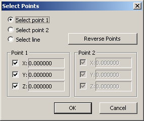
Select Points dialog box
Instead of typing an offset value, you can use this dialog box to select an offset by simply picking a CAD entity from the Graphics Display window.
|
Dialog Box Item |
Description |
|
Select point 1 option |
This option defines the translation location. With this option selected, click on a desired CAD entity. This anchors the point to that location. |
|
Select point 2 option |
This option specifies the angle with respect to point 1 and the axis of rotation. With this option selected, click on a second CAD entity on your CAD model to define the angle. |
|
Select line option |
Instead of selecting two points for your translation, this option lets you select a single line. PC-DMIS then sets the values of the Point 1 and Point 2 areas to match the start and end point of the selected line. |
|
Reverse Points button |
This switches the XYZ values of Point 1 with the XYZ values of Point 2. |
|
Point 1 and Point 2 areas |
These areas define the XYZ center point of the CAD entity selected with the Select point 1 and Select point 2 options. The check boxes in these areas allow you to selectively update the X, Y, or Z value of the point, enabling you to specify points where there is no actual geometry for you to click on. For example, for Point 1, suppose you wanted the X and Y value of one point but the Z value of a different point. To do this, you would clear the Z check box and then select one point. Then you would clear the X, Y check boxes, select the Z check box, and then select the other point. |