Click Alignment
![]() from
the Tools toolbar or select
the Tools | Alignment
menu item. This opens the Alignment
dialog box.
from
the Tools toolbar or select
the Tools | Alignment
menu item. This opens the Alignment
dialog box.
Once you have created features, you can create or modify alignments:
Click Alignment
![]() from
the Tools toolbar or select
the Tools | Alignment
menu item. This opens the Alignment
dialog box.
from
the Tools toolbar or select
the Tools | Alignment
menu item. This opens the Alignment
dialog box.
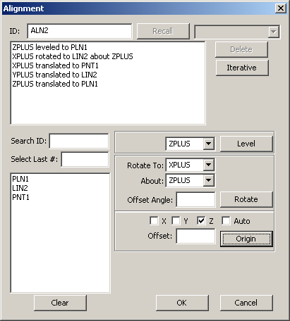
Alignment dialog box
If needed, type an ID for the alignment in the ID box.
Select the feature and the axis (from the drop-down box next to Level) to which the alignment will be leveled. Click Level to define the leveling component to the Active Alignment list.
Select the feature, Rotate To axis and About axis (from the drop-down boxes next to Rotate) to which the alignment will be rotated about. Use the Offset Angle value to adjust the rotational offset angle from the nominal rotation to the specified feature. Click Rotate to define the rotating component to the Active Alignment list.
Select the feature to which the selected origin axis/axes of the alignment will be established. Choose one or more XYZ axes or the Auto option. Click Origin to define the translated component(s) to the Active Alignment list. The Auto will choose the axes to move based on the feature type, the orientation of that feature, and the workplane.
Note:
When selecting features use the following dialog box options:
· Typing the needed feature
name in the Search ID box and
the feature will be highlighted in the Feature list box when you press
the TAB key.
· Selecting the last of a certain
number of features by typing the needed number in the Select
Last # box. For example, if you wanted to select the last four
features that were created, simply type 4 and press the TAB key. PC-DMIS
will highlight the features selected in the Feature
list box.
· Click Clear
to clear the previously selected features.
Click OK to add the alignment to the Inspection Plan, or click Cancel to close the dialog box without saving.
See the "Creating an Iterative Alignment" topic for Iterative Alignment information.
More: