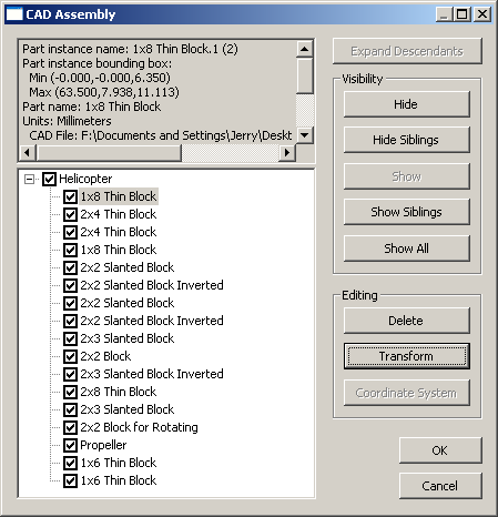
The CAD Assembly dialog box allows you to control the display of the elements of an imported assembly file. Hiding or showing assembly parts will affect the display of that part in the Graphics Display Window as well as the corresponding entries in the Inspection Plan.

CAD Assembly dialog box
Note: When a part or assembly is selected from the list, the corresponding part or assembly is highlighted in the Graphics Display Window.
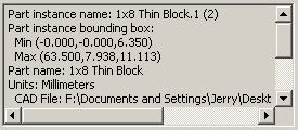
To view information about a part or assembly:
Select either an assembly entry or a part entry from the list of assembly components. Part or assembly information is displayed.

Review the part or assembly information.

The CAD Assembly dialog box uses the following controls:
Expand Descendents: Expands the list for the selected assembly item with a plus (+) sign so descendent (included) parts are shown.
Hide: Hides the selected part or assembly from display in the Graphics Display Window. You may also do this by deselecting the checkbox next to the part or assembly name.
Hide Siblings: Hides all other parts included within the same assembly as the selected part from display in the Graphics Display Window.
Show: Displays the selected part or assembly in the Graphics Display Window. You may also do this by selecting the checkbox next to the part or assembly name.
Show Siblings: Displays all other parts included within the same assembly as the selected part in the Graphics Display Window.
Show All: Displays all parts and assemblies in the Graphics Display Window.
Delete: Permanently removes the selected part from the assembly.
Transform: Opens the CAD Transform dialog box for the selected part. See "Transforming CAD".
Coordinate System: Opens the CAD Coordinate System dialog box for the selected part. See "Changing the Graphic Mode".