Using the Auto Features Geometry toolbar or the Features menu you can create and add features to your Inspection Plan.
![]()
If a plan does not exist, you can create a feature and IP will automatically create a new plan for you. Otherwise, select the needed Inspection Plan from the plan list and begin creating features by doing the following:
From the Auto Geometry Features toolbar or the Features menu, select the feature type you want to create (listed below). A dialog box, specific to the selected feature, appears.
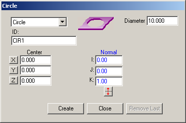
Example Circle dialog box
Inspection Planner supports the following features:
|
|
Surface Point |
|
Circle |
|
Polygon |
|
|
Edge Point |
|
Ellipse |
|
Cylinder |
|
|
Angle Point |
|
Square Slot |
|
Cone |
|
|
Corner Point |
|
Round Slot |
|
Sphere |
|
|
Line |
|
Notch Slot |
|
|
|
|
Plane |
|
Flush & Gap |
|
Using the mouse, select the face, edge, or vertex from the CAD display that will be used for the feature. The feature is created with the nominal data extracted from the CAD data. You can create multiple features for the given type by selecting from the CAD until you have created the needed features.
Edit the values from the "Feature" dialog box as needed. See "The Auto Feature Geometry Dialog Box" topic for more information on each of the available settings. Also, see the "Creating an Edge Scan Feature" and "Creating a 3D Scan Feature" topics for information on creating scan features.
Click Close or Create when you are done. Click Remove Last to remove that last feature that was created via selection if the result is not acceptable.
More: