Example of Reference Plane for a Circle
A - Reference plane as determined by hits on surface.
B - Measured Circle as determined by hits inside of circle.
C - Nominal Circle position where measured circle is projected to the reference plane.
2D Features such as a circle require the use of a reference plane to establish the feature's position. The reference plane coincides with the feature's nominal values. For example, a circle's nominal position is created at the location where the measured circle of a hole is projected to the surface where the hole resides.
|
|
Example of Reference Plane for a Circle A - Reference plane as determined by hits on surface. B - Measured Circle as determined by hits inside of circle. C - Nominal Circle position where measured circle is projected to the reference plane. |
If you begin measuring a circle feature and there are no previously measured reference planes, you will be required measure a reference plane.
Features that require a reference plane are:
To measure a reference plane:
Begin measuring a feature where a reference plane is required.
If no reference plane exists in your part program, the reference plane QuickStart interface will open to create a reference plane.
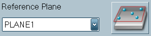
If a plane does exist, but you still need to measure a new reference plane, click the [New Plane button] next to the Reference Plane drop-down list.
|
|
|
|
|
Note: If you are not satisfied with a hit, you can remove it by clicking the Remove Hit button. You can also hold the Done (middle) button for more than one second to remove the last hit.
Note: Features excluded from the report do not require you to define nominal and tolerance values. |
|
|
|
|
|
Select the check box next to the new reference plane in the History window to toggle the display of the plane's flatness dimension in the report. |